

How Does a Paper Bag Machine Work? Step-by-Step Industrial Manufacturing Process & Mechanics
How Paper Bags Are Manufactured: Step-by-Step Industrial Converting Mechanics
Commercial paper bag conversion replaces manual folding with a continuous high-speed web process. Each processing zone must maintain physical dynamic equilibrium across varying paper web weights (from 45 gsm recycled agro-kraft up to 150 gsm virgin kraft roll stock):
Stage 1: Tension-Controlled Unwinding & Ultrasonic Web Guiding (EPC)
The raw kraft paper reel (weighing up to 1,500 kg) is mounted on a pneumatic expanding shaft with hydraulic lift loading. Web tension is governed by a closed-loop servo brake or dynamic magnetic powder brake, regulated via dancer roller potentiometers to maintain continuous tension (50–120 N ± 1.5 N) as reel diameter shrinks. Concurrently, an ultrasonic Edge Position Control (EPC) sensor monitors web drift, driving a motorized shifting pivot base to keep web lateral deviation within ≤ 0.2 mm.
Stage 2: Longitudinal Side-Seam Gluing & Perforation Pre-Creasing
Before web encasement, a metered film of water-based polyvinyl acetate (PVA) cold adhesive is laid along the paper edge via an adjustable wheel or pneumatic extrusion nozzle. Synchronized rotating creasing wheels score longitudinal folding lines across the continuous web. This pre-creasing softens paper fibers, ensuring clean, sharp side gussets without surface fracturing or structural delamination at high speeds.
Stage 3: Continuous Tube Forming with Gusset Creasing
The flat paper web passes over a geometric former plate and adjustable roller collars, bending inward into a hollow paper tube. Driven side-gusset disks tuck both lateral edges inward to shape the M-fold gussets. The glued edge overlaps the dry edge, passing beneath weighted pull-down draw rollers that bond the continuous seam under uniform compression.
Stage 4: Servo-Driven Photoelectric Tracking & Rotary Cutoff
For printed bags, a German or Japanese high-frequency optical registration sensor detects printed eye-marks on the moving tube. A high-speed rotating cutter drum, driven by an independent motion servo motor via Electronic Cam (E-Cam) curves, accelerates and decelerates dynamically to execute clean shear cuts at the precise bag pitch. This dynamic velocity profiling restricts cut length variations to ≤ ± 0.5 mm at line velocities exceeding 180 m/min.
Stage 5: Bottom Opening, Scoring, and Cross-Gluing Drum
Individual cut tubes transfer onto the central bottom-forming drum. Mechanical gripper fingers and vacuum suction cups pull open the lower leading edge into a flat diamond/rhombus profile. Controlled rotary paste fingers apply cold glue patterns onto the folded flaps, while synchronized folding blades tuck the lower and upper flaps inward in rapid succession, closing and sealing the square block bottom (SOS).
Stage 6: Pressure Compaction, Counting, and Automated Discharge
The formed bags pass between two wide, spring-loaded flat rubber compression belts. This stage expels trapped air and cures the water-based adhesive under mechanical dwell pressure. A pneumatic kicker shifts every 25th or 50th finished bag laterally on the horizontal discharge conveyor, allowing packing personnel or automated robotic arms to package bundles directly into cartons.
Mechanical Synchronization Architecture: Multi-Servo Electronic Line Shaft (ELS)
Older converting machinery relied on a physical main drive shaft connecting gears, chains, and change-gears. Changing bag cutting length required an operator to manually dismount and swap gear clusters, consuming 2 to 4 hours of machine downtime.
Modern industrial equipment, exemplified by the OYANG TECH-18 Automatic Paper Bag Machine, replaces mechanical linkages with a multi-axis digital servo bus system (EtherCAT/PROFINET):
Motion Controller
Continuous Feed Velocity
E-Cam Speed Profiling
Gripper & Fold Phasing
Figure 1: Closed-loop digital ELS topology showing real-time bus-synchronized slave axes tracking a software master reference.
Under Electronic Cam (E-Cam) control, the rotary cutting blade does not spin at a constant rate. Instead, it matches web feed speed exactly at the instant of shear cutting, then accelerates or decelerates during the remaining 300 degrees of its rotation according to the bag length programmed on the touchscreen. This software synchronization enables 2-minute digital bag size changeovers with zero mechanical gear changes.
Converting Process Control Specifications & Tolerances
The following matrix defines acceptable industrial engineering tolerances at each converting station during continuous commercial runs:
| Process Stage | Key Mechanical Subsystem | Critical Operating Parameter | Standard Tolerance Limit |
|---|---|---|---|
| Unwinding / Feeding | Pneumatic shaft & ultrasonic EPC | Web edge alignment & dynamic tension | ≤ ± 0.2 mm lateral drift; ± 1.5 N tension |
| Side Gluing | Pressurized extrusion nozzle / paste disc | Adhesive film thickness & seam width | 12 ± 1.0 mm seam width; 0.15 mm glue film |
| Tube Cutoff | Servo rotary shear blade & optical mark sensor | Cut length repeatability & squareness | ≤ ± 0.5 mm cut length; ≤ 0.3 mm diagonal skew |
| Bottom Forming | Suction drum, opening fingers, paste wheel | Bottom fold overlap & paste coverage | ≤ ± 0.8 mm overlap; 100% leak-proof seal |
| Discharge & Stacking | Flat double-belt press & pneumatic counter | Curing dwell pressure & count accuracy | 0.2–0.4 MPa contact pressure; zero count error |
OYANG Engineering Practice: Machining Tolerances for Flawless High-Speed Mechanics
In paper bag machinery running at 220 bags per minute, mechanical components experience violent cyclical accelerations. If side-frame bearing housings or rotary knife mandrels display concentricity deviations exceeding 0.02 mm, high-speed vibrations cause premature bearing wear, cutting blade micro-chipping, and uneven bottom paste distribution.
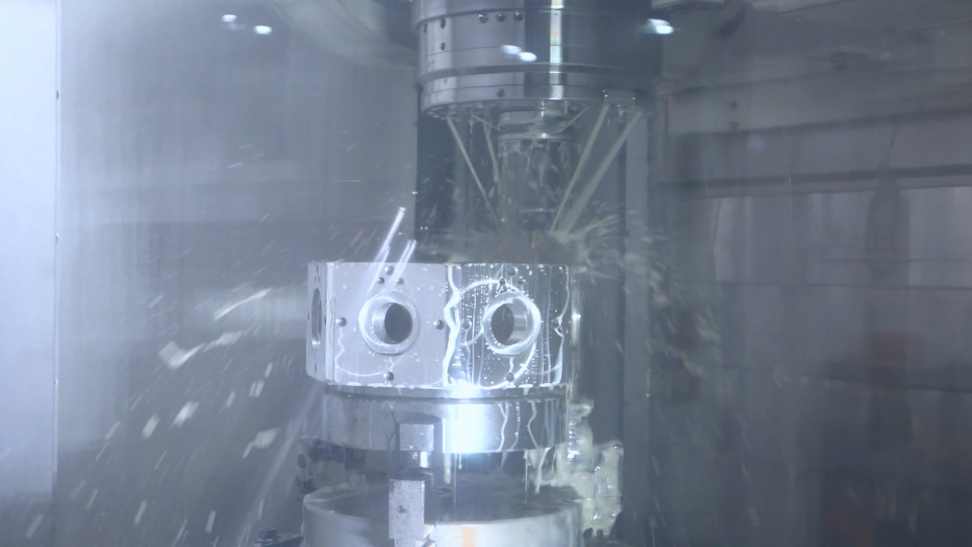
Figure 2: Japanese OKUMA precision horizontal machining centers milling structural bag machine components at OYANG’s 130,000 m² production complex.
To prevent mechanical harmonic distortion, all structural machine walls, folding drums, and cutting mandrels at OYANG are processed using Japanese MAZAK and OKUMA CNC multi-axis machines to tolerances of ≤ 0.015 mm. This structural rigidity ensures stable web tracking and enables continuous production with web scrap rates below 1.2%.
Brochure Download: Review exact mechanical dimensions, pneumatic ratings, and power requirements in the OYANG Paper Bag Machine Solution Brochure (PDF).
Video Demonstration: Observe the complete 6-stage bag forming sequence on the OYANG 16A Fully Automatic Paper Bag Production Video.
Related Engineering Guides & Technical Resources
Frequently Asked Questions (FAQ)
How does a paper bag machine work?
A paper bag machine works by unwinding kraft paper rolls under closed-loop tension control, applying water-based adhesive along the edge, folding the continuous web into a tube via former plates, cutting the tube to length with a servo-synchronized rotary shear knife, and using suction drums and gripper fingers to open, paste, and fold the square or sharp bottom before final compression stacking.
How are paper bags manufactured step by step?
Paper bags are manufactured step by step through six synchronized stages: (1) paper reel loading and ultrasonic edge position guiding, (2) side-seam gluing and gusset creasing, (3) continuous tube formation, (4) high-speed rotary cutoff driven by optical mark tracking, (5) bottom opening, glue application, and bottom folding, and (6) flat belt pressure curing and automated counting.
What is the difference between SOS square-bottom and V-bottom paper bag machines?
An SOS (Self-Opening Satchel) machine utilizes a complex bottom-forming drum with suction cups, paste wheels, and mechanical folding fingers to construct a flat rectangular base capable of standing upright, ideal for groceries and retail. A V-bottom machine uses a simpler rotary knife and pinching blade to fold and seal a flat, sharp envelope bottom, running at faster speeds for bakery and pharmaceutical packaging.
How does an electronic line shaft (ELS) improve paper bag making?
An electronic line shaft (ELS) replaces physical mechanical drive shafts, chains, and gear sets with bus-synchronized multi-axis servo motors. Motion controllers use Electronic Cam (E-Cam) algorithms to automatically adjust rotary knife acceleration, draw roll pitch, and drum phasing, eliminating mechanical backlash and enabling 2-minute digital bag size changeovers via touchscreen recipe recall.
How do you start making paper bags in an industrial factory?
Starting industrial paper bag making requires loading raw kraft reels onto an automated roll-fed converting line, threading the paper web through dancer tension rollers and edge-guiding sensors, setting the side-seam and bottom glue paste volumes, inputting target bag length and gusset parameters on the motion controller HMI, and setting the operating speed for continuous production.